
A pdf version of this article is available on the right-hand side under 'Downloads'
Hydraulic systems waste much of their energy as the fluid circulates at a constant pressure, regardless of the amount of work carried out. Despite this, drives are not widely used in hydraulic installations, perhaps because the very impressive savings normally achievable in standard pump applications are not possible with the type of pump used in hydraulics. However, when Corus Colors, Deeside, UK looked closely at the issue, the company found that significant energy savings could be achieved.
A trial was carried out by Rob Chew, a graduate engineer at the Corus Colors, and Phil Tomkinson of Radway Control Systems. The aim of the study was to establish whether the drive would be a viable option for controlling energy consumption in hydraulic systems.
The hydraulic system used during the trial is located on a production line used for retreating and inspecting strip material, driving actuators and web guiding systems in a 24-hour process.
“As drives can be used to accurately control the speed of most motor driven machinery, hydraulic pumps should be no exception in this respect,” says Chew. “Hydraulic systems waste much of the energy used, because fluid circulates continuously, although actuation is only required for very short periods of time.”
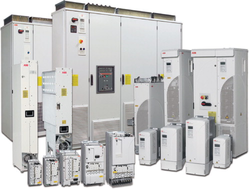
The energy used by the pump can be controlled by intelligently modulating the speed of the motor. The particular function used in this trial was the PID control, built into the ABB drive, which helps keep external values, like pressure, within certain limits. Pressure feedback is returned to the drive from a transducer. The drive automatically adjusts pump speed to maintain the system pressure.
Saving potential
Drives tend not to be used much on hydraulic systems, usually because the pressure is normally provided by a positive displacement pump, a type of pump that, theoretically, offers far less energy saving potential than the more common centrifugal pump.
Unlike a centrifugal pump, which uses centrifugal force to throw fluid out through the discharge end of the pump, the positive displacement pump uses an internal mechanism that presses the fluid out. This means the output will be the same regardless of the resistance on the discharge side. The internal mechanism can be some type of gear or an arrangement with vanes. The installation at Corus Colors uses a positive displacement vane pump, driven by two 37 kW motors, one duty and one stand-by.
Under pressure
Positive displacement pumps are used in hydraulic systems because this type of pump can produce high pressure despite high system resistance. A centrifugal pump is far less effective working against a high system pressure. Its actual capacity can be anything from 0 to 100% of full capacity, depending on the resistance produced by the system pressure. Because the pressure in a hydraulic system is very high, a centrifugal pump would not be able to pump much at all against this resistance. A positive displacement pump, in contrast, only shows a very small change of flow when the pressure goes up or down.
However, the energy consumption of the positive displacement pump is not reduced when the system resistance drops. For this reason, it does not offer the same energy saving potential as centrifugal pumps at reduced speed. While the centrifugal pump offers energy savings equal to the cube of the speed reduction, a change in flow by the positive displacement pump produces a linear change in power usage.
But despite using a positive displacement pump, Corus Colors achieved significant energy savings by retrofitting the existing system with a drive. The pump speed was greatly reduced both when the system was in neutral and during actuation of the cylinders.
Optimising speed
Chew's trial aimed to establish whether system pressure could be maintained with reduced average motor speed, using a drive, with pressure data fed back to the PID control of the ABB drive from a pressure transducer. The installation was commissioned on a downshift as other maintenance was carried out on the production line.
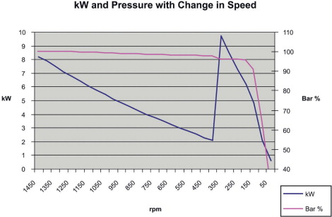
Vane pumps start losing their efficiency below 400 rpm, as the vanes are held in position by centrifugal force, so the pump efficiency had to be monitored throughout the trial as the optimum speed was sought. This was eventually established to be 450 rpm.
Chew had concluded that leaving the drive just running in PID control would cause some unwanted side effects. The main issue was that a drop in pressure would be followed by an increase in motor speed in response to the pressure drop.
The desired system pressure is 90 bar, while the maximum is 93 bar at full speed. As in many hydraulic systems, the on-load times are short. After actuation of the cylinders, the hydraulic system quickly settles back into neutral again. As the drive will have increased the motor speed rapidly to meet the drop in pressure, it is likely that it would overshoot the target of reaching a pressure of 90 bar, with the PID control having been set very high for a fast response.
The system relief valve is activated at 93 bar so the system pressure will never get higher that this. As the drive only sees a small error in pressures of 3 bar, it may be slow to react. This means there will be a long transient time before the drive settles down to the required speed to maintain 90 bar in neutral and this will cause unnecessary waste of energy, sending excessive fluid back to the sump while the hydraulics are in neutral.
Dual mode control
The solution was to operate the drive in two modes, PID control and single-speed mode. The switching between the modes is controlled by the transistor output of the pressure transducer. When the hydraulic system is in neutral and the pressure is at the desired level, the drive runs at a single speed of 450 rpm, the optimum speed established through the trial.
When the system is operated and the pressure drops, the transducer switches the drive into PID control. The desired pressure set in the PID is 93 bar, the maximum pressure for the system, and the proportional control is set very high to ensure a rapid response from the drive. Once the pressure increases to 90 bar, the transducer will switch the drive back to single speed mode. This will prevent any overshoot in speed and reduce energy waste.
The drive's hysterisis control is used to stop rapid switching which could wear out components and pulse the motor excessively.
Energy saving
Once Chew had established the optimum speed, wired up the transducer and programmed the PID control, the installation was monitored for two days to compare the energy consumption between under drive control with direct-on-line operation. Energy consumption was measured before and after using an energy meter.
When in neutral, power consumption was around 9 kW with direct-on-line operation. Under drive control, power consumption was reduced to 2 kW, a reduction of 77%. With the system under load, power consumption was reduced from 22 kW to 12 kW, a saving of 48%. As the on-load duty time for the system is 16%, the average energy saving over time was 70%.
“The reduction in energy consumption under load initially surprised me, as it should take the same amount of energy to move a hydraulic cylinder a given distance regardless of whether a drive or direct-on-line operation is used,” says Chew.
Reduced power
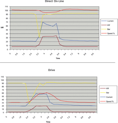
An experiment was set up to test the hydraulics in direct-on-line operation and under drive control with a single actuation on the largest cylinder. To record the readings, the drive's internal recorder was used with the DriveWindow software from ABB. This gave high sample rates over a short period of recording time. The drive was set up to run at a single speed of 1470 rpm to the mimic direct-on-line operation. The recording was then started and the cylinder actuated five times, once every five seconds. The procedure was then repeated with the drive in the dual mode setup with PID and single speed. The readings showed a similar performance between the two tests but a vast difference in energy consumption, the drive peaking at 20 kW while the system in direct-on-line mode peaked at 34 kW.
“The test showed that the drive used a lower motor speed to achieve the required pressure,” says Chew. “The flow rate will be lower, but the drive is still fully capable of matching the response times of a direct-on-line configuration.” The reduced energy consumption will allow a payback time of just 18 months and reduce the company's carbon footprint by 33 tonnes of CO2 annually.


