
Undoubtedly pumping is one of the largest application areas for AC inverter drives. However, due to current power conversion technologies, including the input rectifiers in PWM (pulse width modulated) inverter drives, very significant harmonic currents (i.e. currents that are usually integer multiples of the fundamental frequency) are produced. These currents have a detrimental effect on the performance and reliability of other equipment and distort the applied voltage.
Nowadays, electricity supply companies place strict limits in order to restrict the harmonics exported to the network. In the USA, and often internationally, the recommendation followed is IEEE 519 (1992) and in the UK it is ER G5/4-1. A number of harmonic mitigation methods have been developed to reduce the harmonics produced by AC drives (that is, to try and isolate the AC drives from the network as far as harmonics are concerned). They include multi-pulse drives (for example, 18 pulse and 24 pulse), active filters and Lineator wide spectrum filters.
However, there is another ‘harmonic reduction’ technology marketed by some companies called ‘active front end’ (AFE) drives where the information provided to the customer can be very, very selective. The object of this article is therefore to provide the reader with a factual understanding of what are often sold as ‘harmonic-less drives’.
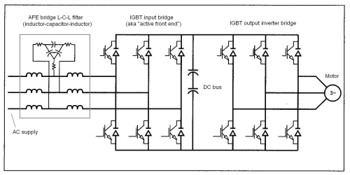
Standard AC PWM drives comprise an input uncontrolled diode-based rectifier, DC bus and IGBT (insulated-gate bipolar transistor) output inverter stage. In an AFE drive, the input rectifier is replaced with another IGBT bridge, as illustrated in Figure 1.
Harmonic-less drives?
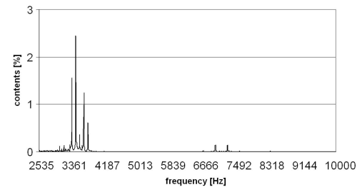
AFE drives are not ‘harmonic-less’ as marketed by some companies; indeed, far from it. The total harmonic current distortion (Ithd) can be <5% but 6–9% is more common However, this is the Ithd only below the 50th harmonic. AFE drives can produce almost the same amount of harmonic currents above the 50th harmonic as below, mainly around the switching frequency of the AFE bridge (for example, around 3 kHz, which is the 60th harmonic if the supply is 50 Hz; see Figure 2. Most current power quality analysers only measure up to the 50th harmonic. This, coupled with ER G5/4-1 not currently considering anything above the 50th, prevents the ‘real’ voltage and current distortions (i.e. <100th) from being appreciated. It should be noted that the heating effect per amp is increasingly larger for higher-order harmonics, leading to a greater potential for harmonic-related problems within the installation and possibly on the network. Some marine classification bodies have realized this problem and are starting to insist that on vessels with AFE drives the harmonics up to the 100th are measured.
Voltage ripple
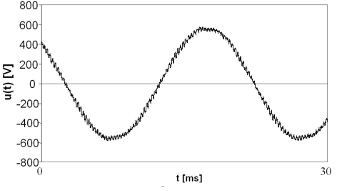
The harmonic currents due to AFE bridge switching can be reduced by the careful design of the front end passive carrier L-C-L filter, which is required to clean the voltage and attenuate the switching frequency ripple. However, this is usually at the expense of higher total harmonic voltage distortion (Vthd) fed into the supply. AFE drives can also produce significant high-frequency harmonic currents well above the 100th. Indeed, on a recent marine project, special EMC (electromagnetic compatibility) filters for operation between 10 kHz and 100 kHz had to be installed between the supply and the bridge to prevent excessive conducted disturbances from AFE drives upsetting sensitive equipment. The quality of the voltage wave measured is shown in Figure 3.
Lower efficiencies
The efficiency of AFE drives (including the L-C-L filter) at the rated load is in the region of 93–94%. Standard 6 pulse drives with an active filter or passive Lineator wide spectrum filter, both of which can often offer harmonic mitigation performance on a par with the more high-performance AFE drives (<50th) but without producing harmonics >50th, have 6 pulse drive/filter efficiencies of around 95–96% and 97%, respectively. The running costs of AFE drives are significantly greater than using standard ‘6 pulse’ drives with either active filters or Lineator-based mitigation.
Reliability issues?
Reliability is paramount for any drive. AFE drives are more complex than standard 6 pulse drives and therefore are inherently less reliable and more difficult for local engineers to repair. If the AFE fails, the drive is down until it is repaired. Experiences in the Middle East and elsewhere have illustrated to me what this means in reality if used on air conditioning or water pumping applications. Were a parallel active filter mitigating 6 pulse drives to fail, the drives would still function fully, albeit with harmonics. Similarly, were a passive wide spectrum filter to fail (which is very unlikely) then it could be bypassed either manually or automatically.
Possible generator interaction
There are also issues regarding the interaction between AFE drives and generators with regard to the reactive current impressed on the source by the front end L-C-L filter capacitors when the AFE drive is switched off but the filter still energized or when, as is common in water or sewage pumping applications, the drives are ‘quiescent’ (that is, powered up but waiting for a start command). The reactive current is uncontrolled and can result in over-excitation of the generators and subsequent tripping unless the filter capacitors are disconnected when the AFE is not actually running. Ideally, for successful applications, the system short circuit power should be 20 times that of the connected AFE drive(s) power. However, this is often impractical due to generator physical sizes and economics. This problem can occur on utility transformer-based supplies but often goes unnoticed.
Interaction with standard AC drives?
There is significant evidence from around the world that AFE drives and standard 6 pulse AC PWM drives can interact when connected to the same bus. The high-frequency currents from the AFE drive force up the DC bus voltage on the standard drives by up to 15%. Whilst this is perhaps beneficial at high load levels, at light loads there are serious risks of tripping the 6 pulse drive(s) due to over-voltage.
Electrical braking for pumps?
Some manufacturers are marketing AFE drives as ‘regen drives’ for centrifugal loads. The requirement for a low harmonic current footprint is that large reactors are used in the AFE L-C-L filter, usually around 13%–16% reactance. This usually precludes the ability to brake regeneratively. ‘Regen drives’ require much less filter reactance in order to function but have higher voltage distortion. Perhaps this is why at least one company lists two AFE drive models for each kW rating.
Transparency required
AFE drives can offer excellent performance as can correctly applied active filters and Lineator wide spectrum filters. However, in terms of cost it has to be said that AFE drives are often the most expensive per kW based on first cost, maintenance costs and running costs over the life of the drive. AFE are simply one possible choice in the range of harmonic mitigation options.
Every application has to be judged on its merits. The successful application of any form of harmonic mitigation is dependent on a sound understanding of harmonics, of the drives, other non-linear loads and of the complete power system. It should not be based on what the salesman wishes to sell the customer.
In my experience and that of many others, some companies marketing AFE drives are guilty of being very selective concerning what the customer is told and, in my experience, can be ‘economical with the truth’ in the push for sales. (For example, recently I have heard an utterly outrageous claim by a major drives company that now also produces active filters that its ‘solution’ offered around four times higher performance than anybody else's – but that won them the order.)
No form of harmonic mitigation is perfect. Some are better than others but customers need to be given all the facts, not a ‘cherry-picked’ selection, in order to make the required, informed judgements to fully assess the best solution for their application.


