
The removal of phosphate from the effluent of a sewage works is an essential part of the UK urban wastewater treatment and related directives. Today, many more treatment works have phosphorus discharge consents but, with the continuing high levels of phosphate in untreated water, the problem of staying within consent is growing. Phosphate removal is carried out by dosing chemicals, normally iron, or occasionally aluminium, salts. The chemicals used in the process are expensive, which is why it is in the interests of wastewater treatment plants to exercise strict control of the dosing regime.
Partech Instruments of St Austell in the UK has developed closed loop feed forward control of inlet dosing systems for the removal of phosphate, which has been trialled successfully at various sites throughout the UK (Figure 1). The results of the trials demonstrate that this approach is reliable and cost-effective, and can assist in achieving optimum dosing pump performance and making considerable savings in chemicals.
Where applicable, the natural removal of phosphate (by naturally occurring biological or chemical precipitation) is the method of choice. However, in most cases it is not possible and it becomes necessary for the works operator to resort to chemicals, with ferric chloride and ferrous sulphate being the most commonly used. Where the efficiency of iron is much reduced, an aluminium salt has been applied successfully and works normally in conjunction with iron salts. In all cases, the amount of chemical used is critical for the performance of the works, cost control and meeting the discharge consent for both phosphate and iron/aluminium.
Dosing iron salts at the front end of a works requires a level of pump control to ensure that the pH of the influent does not become too acidic as this has a detrimental effect on the nitrifying process. Historically, the iron dosing rate was calculated by taking a series of samples throughout the day and having them analysed to derive a diurnal profile. This profile was entered into the dosing system such that a specific volume of iron was dosed at the time intervals used and this was then employed to ‘control’ the dose.
Sampling system
The Partech sampling system is based around analysing orthophosphate, as opposed to total phosphorus; orthophosphate chemistry is simple and fast, while total phosphorus chemistry is more complex and can be very slow. Iron reacts directly with the soluble phosphate, which is almost totally in the orthophosphate form. The total phosphorus is largely in the bound form with the solids and therefore naturally settles along with the treated soluble form of phosphate. In order to analyse for total phosphorus, it would also be necessary to analyse an unfiltered sample, which in the inlet application would not be possible.
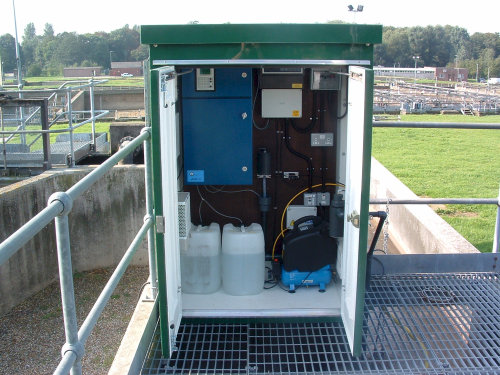
The measurement system uses the MicroMac C analyser, which incorporates a loop flow analysis (LFA) system. The highly flexible LFA technique allows the analyser to cope with the high level of background turbidity associated with raw sewage. The analyser uses a chemical method that is directly comparable to the Blue Book method used in laboratories, thus allowing direct comparison with any grab samples analysed in a laboratory. (The Blue Book is published by the UK Environmental Agency's National Laboratory Service. Its Statutory Committee of Analysts provides authoritative guidance on methods of sampling and analysis for determining the quality of environmental matrices.)
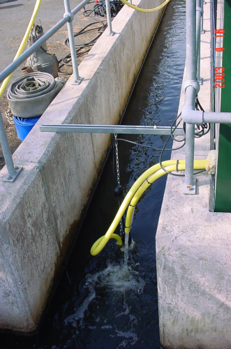
Throughout the trials, Partech gave great attention to designing a sampling system that would be low maintenance and ensure reliable crude sewage sampling. The sampling system is a critical part of the control system and requires an optically clear sample to determine the orthophosphate level accurately, this being achieved by the use of filtration technology to remove solids from the sample. The finished design copes with low flow and low sample levels, grit, ragging and turbulent flow (Figure 2). In addition to low maintenance, the simple design helps with operator confidence and keeps the cost to a minimum.
The advantage of determining the phosphate level at the inlet is that the dose rate of the iron or aluminium salt can be calculated and the dosing pump system controlled using the combined flow and phosphate concentration. The combined output generated allows the operator to adjust the dosing pumps for site-specific conditions that allow the ‘P to Fe’ ratio to be adjusted until it is optimized. This optimization requires the monitoring of the final effluent to ensure that the phosphate levels are within the Environment Agency consent and once the optimization has been done there is no need to further monitor the final effluent. Whilst not essential, an analyser measuring total phosphorus to monitor the discharge consent may be used here as orthophosphate is being measured at the inlet.
By using feed forward control, the dosing pump responds to actual changes in phosphate levels and provides an active dosing regime. In contrast, the commonly used ‘diurnal profile’ cannot respond to changes in the inlet and can be either over- or under-dosing, both of which have financial consequences. Alternative feedback control can be employed at some sites but tends to offer poor control due to time lag between the dosing and measuring points. The slow-moving sewage treatment process with residence times of many hours in settlement tanks and aeration basins benefits from feed forward control. Partech's measurement system makes this possible, operating where alternative systems cannot be applied.
Dosing system
All of Partech's chemical dosing systems follow the same basic pattern even though they can look very different. Each system has two chemical holding tanks that can be isolated to allow for maintenance. Chemical passes out of the holding tanks through a series of isolation valves to the inline filters. These filters remove debris from the chemical, which can reduce the pumping efficiency, or block up valves upstream of the pumps. These filters need regular cleaning, and are the most common cause of problems within the dosing system. If they become blocked the pump is not able to deliver the required dose rate. It is advisable to clean both filters prior to calibrating a pump.
Once the chemical has been through the filters it passes to one of two dosing pumps (duty/standby) for each dosing point. Some sites have more than one dosing point, in which case there will be individual dosing systems for each dosing point.
After each pump is a pressure relief valve. If there is a blockage downstream of the pumps and the pressure within the system reaches that required to open these valves then the chemical will pass either back to the holding tanks (through the overflow lines) or to the bund depending on the type of system. Thereafter, the discharge from both pumps joins a common line so all subsequent items are common to both pumps.
The next item in the flow path is the pulsation damper. The pumps push the chemical forward in pulses and the damper smoothes these so that the chemical is delivered to the dosing point in a constant stream. The damper is at 10 bar pressure. After the pulsation damper is a flow monitor, which detects if the chemical flow rate drops below an adjustable set point. If this happens the duty pump has failed, the standby pump is brought on and an alarm raised. If the standby pump fails to deliver the minimum flow rate then that pump is also failed and a higher priority alarm raised.
After the flow monitor is a pressure gauge that shows the pressure in the dosing system and the back-pressure on the pumps. It can be used to determine the cause of a problem if the system is not working properly, i.e. if the loading valve, which is the next item in the flow path, is blocked and chemical is passing through the pressure relief valves. Depending on the site, the pressure shown on the gauge may not be zero when the pumps are not running due to the back-pressure from the loading valve. The gauge is also used to set the loading valve.
The loading valve has two purposes. The first is to stop chemical siphoning from the holding tanks to the dosing point. The second is to ensure there is a back-pressure on the pumps so they deliver the dose that they should for a given speed. If the pressure imposed by the loading valve is changed, then the pumps must be recalibrated.
Once the chemical has passed through the loading valve it travels to the dosing point via the dosing line. The calibration pot is used to measure how much the pumps are dosing and if the stroke setting on each pump is right for the required dose rates. The flushing valves are points on the dosing system where lines can be connected and used to flush potable water (not final effluent) through to clean out any chemical before maintenance work is carried out. There is usually one emergency stop button for each pump set. This will fail both pumps.
Trial sites
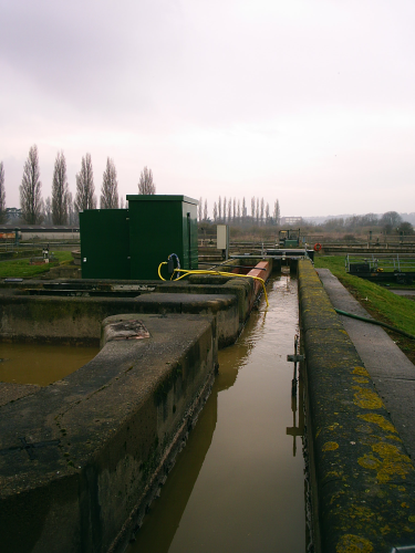
Four water companies provided sites for Partech's evaluation programme: Thames, Wessex,Southern and Anglian Water. The Thames Water site, with a population equivalent (PE) of 39 000, had a pumped inlet and a Gee & Co system dosing ferric sulphate controlled by a predetermined diurnal pattern. The inward flow varied between 40 and 200 litres per second and upstream of the measuring point was a weir below which were two ‘sandbanks’ that released significant amounts of grit during high flow.
The trial unit was positioned above the inlet channel some 20 m upstream (Figure 3) of the dosing point and the sample pump was located directly below the trial unit. The flow signal was obtained from an existing flow meter. After four months the system was reliably analysing crude sewage for orthophosphate and, when combined with the inlet flow, was successfully controlling the dosing system. During the initial stages, Partech was able to demonstrate a saving of some 25% of the iron dosed compared with the diurnal dosing regime. This was later improved by a further 8% by adjusting the ‘P to Fe’ ratio.
Wessex Water's Keynsham Sewage Treatment Works is a pumped inlet works with a population equivalent of 23,000. It has total phosphorus consent of 2 mg/litre as P and uses ferric sulphate dosed by a Michael Smith Engineering Ltd dosing system. The aim of the trial was to demonstrate that the control of the iron dosing system by a combination of phosphate level and flow provides a cost benefit due to the reduction in the amount of ferric sulphate (12.5% Fe) solution used.
An orthophosphate monitor was sited at the inlet to the works after the screens and before the iron dosing point. The current (mA) output from the existing flow meter was sent to the monitor and combined in a PR electronics module with the phosphate mA output and an algorithm applied to provide a single mA output to the dosing unit.
The trial lasted for 14 days, during which periods of ‘control’ and ‘no control’ were used. ‘No control’ means using the traditional method of setting the dose level. A portable analyser was used to measure the phosphate level in the final effluent to evaluate the efficiency of the phosphate removal process and to ensure the effluent was compliant during the trial.
Initially, the iron to phosphate ratio was set such that the output from the trial unit mimicked the existing dose mechanism, that is, a factor of 3. After a period of days this factor was reduced to 2.5 to see the difference in dose it made. At this stage a portable analyser was set up to monitor the final effluent.
The trial unit was installed next to the inlet channel just before the flow measurement point in the channel and upstream of the dosing point. The sample pump was situated as close as possible to the trial unit, with the flow signal being obtained from an existing flow meter.
The submersible pump was controlled by the analyser and routinely only operated for c. 90 s per analysis cycle, this being sufficient time for the filter element to be cleaned and the sub sample pot to be filled to overflowing before the analyser collected its sample. This cycle enables the use of a filtered sample without having to manually clean the filter element more frequently than once in three months.
The final effluent was monitored next to the urban wastewater sampling point for ammonia and orthophosphate. The sample was pumped up to the sample pot by a small peristaltic pump through an unfiltered sample line. The data obtained by this system was used to check that any of the adjustments made at the front end did not adversely affect the effluent. By using the phosphate analyser on the inlet to the works it could be possible to stop the dosing of iron completely when the incoming P concentration falls below a certain figure e.g. 3 mg/litre. This would of course introduce another potential saving and could easily be built into the dosing control package.
Summary
With the cost of the Partech control system being in the region of £12 000–£17 000, depending on site conditions, and a saving of 18% per annum at a site with a chemical dosing rate of approximately 400 litres per day at a cost of £50 per tonne, the payback period is less than 12 months.
The use of an ‘active’ control system at the inlet to a works can have the following effects:
1. Tighter and more effective control of the chemical dosing pump unit, with response to routine and non-routine events.
2. Savings of dosed chemical expected to be in the 10–40% range depending on the status of the works as far as optimization is concerned.
3. Less likelihood of consent failure for both residual chemical – Fe or Al – and phosphate.
4. Reduced sludge production.
5. Reduced potential for corrosion of the works due to over dosing of iron.
6. The control system will have a payback period relative to the size of the works and volume of iron being used and is not expected to be viable on a small works.
In summary, a reliable, robust dosing control system for sewage works now exists that optimizes both the dosing pump's performance and the chemicals used.


