
Q. What is water hammer, and what is its impact on a pumping system?
A. Water hammer is also known as surge pressures or hydraulic shock. It is a condition that exists when fluid changes velocity quickly in a piping system. There are several causes of water hammer, but most often in pumping systems it is due to a pump start or stop, a rapid change of valve position, or a valve failure. The velocity change results in a pressure wave that is above and below the normal pressure in the piping system. These pressure waves are called surge pressures or water hammer (when water is the fluid), and their magnitude can be sufficient to burst or collapse piping, valves, machinery casings and other devices.
The pressure wave’s magnitude can be calculated with reasonable precision if the user knows the configuration of the piping, the size of the pipes, the materials of the piping, the properties of the fluid, and how quickly the pump and/or fluid accelerates or decelerates. When the column of fluid in the piping is either started or stopped, the energy of the system is transformed from velocity energy to head or pressure energy. Because the fluid and piping material are not completely incompressible, they will absorb a fraction of the energy.
Water hammer can be understood through proper surge analysis and controlled through proper valve closure rates (with slow-closing valves), controlled starting and stopping of pumps, the addition of diaphragm tanks to absorb the pressure surge, and relief valves to release the pressure.
For more information on water hammer, refer to ANSI/HI 9.6.6 Pump Piping for Rotodynamic Pumps at pumps.org.
Q. How should I design the inlet piping for single and multiple metering pumps?
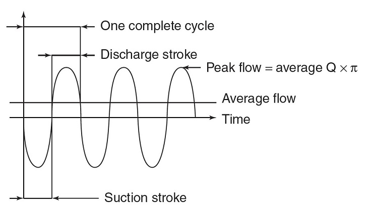
A. Because of the characteristic pulsating flow (Image 1) of controlled volume metering pumps (CVMP), where peak flow rates can reach three times the average flow; therefore, careful consideration must be given to the inlet piping to ensure that it is capable of delivering adequate fluid to the pump inlet.
For all CVMPs, the most frequent reason for technical support calls to pump manufacturers regarding problems with pump performance is because the inlet piping cannot supply the demands of the pump. The following guidance should be followed to ensure adequate flow to the inlet of the pump.
• The pulsating flow in the system inlet piping creates a pulse pressure that typically subtracts from system inlet pressure. For example, a pump operating at 150 strokes per minute and 71 gallons per hour drawing water from 10 ft of 1/2 inch schedule 40 pipe could subtract 10 psi from the pump’s supply pressure. For shorter runs of pipe with a minimum of restrictions, a general rule of thumb is to increase two pipe sizes above the pump’s inlet connection. Long piping runs with multiple bends, elbows, restrictions and/or higher viscosity liquids will require larger size piping.
• The length of pipe and numbers of elbows, tees, strainers, valves, and other accessories installed in the inlet piping should be limited as they decrease the Net Positive Inlet Pressure Available (NPIPA). The NPIPA must be evaluated and designed to an acceptable level for the pump to operate reliably.
• Refer to NPIPA calculations outlined in ANSI/HI 7.8 Control-Volume Metering Pump Piping Guideline. This includes the acceleration head in the inlet piping.
• The inlet piping must accommodate peak demand flow and pressure, and prevent offgassing of liquids with high vapor pressure or dissolved gases. This is generally accomplished by appropriately increasing the diameter of the inlet piping and connections or by adding accessories to increase the flow of liquid to the inlet of the pump.
In addition to the guidance provided above, the other most important consideration for multiple pumps is to determine whether the multiple pumps (heads) are part of a multiplex pump (multiple heads connected to a single motor or driver) or if the heads all have independent motors or drivers.
In most cases, multiplex pumps are connected to a common manifold piping arrangement.
In a multiplex pump where a single driver is used, if the pumps all operate from the same gear set or with multiple gear sets operating at the same stroking speed, industry best practices suggests the drive mechanism for each individual pump head should be run out of phase, i.e., duplex pumps 180 degrees, triplex pumps 120 degrees, and so on.
This is done to stagger the peak suction requirements of the individual pumps. Running several pumps from the same driver (motor) with proper phasing of the drive ensures this timing during all running conditions and thus the best suction flow characteristics as it relates to piping design.
When independent pumps, each with its own drivers are connected to a common suction line, or if the application requires multiplex pump heads operating in phase, allowance must be made in the piping design for the event where all pumps simultaneously demand peak suction flow.
For more information on piping guidelines for control-volume metering pumps, refer to our new standard ANSI/HI 7.8 Control-Volume Metering Pump Piping Guideline at pumps.org.


