
Since the late 1960s oil mist has excelled as an unusually simple and highly dependable lube application method. Compared to traditional liquid oil sumps in pumps and often ill-defined grease applications in electric motor drivers, plant-wide systems today are orders of magnitude more reliable and cost-effective. An estimated 140,000 process pumps and 27,000 electric motors are presently (in late 2014) served by over 3,000 plant-wide oil mist systems.
From five to as many as 70 pumps and/or drivers can be connected to a given system. The technology is widely used in advanced oil refineries and chemical plants; we call them ‘Best-of-Class’ facilities. When electric motors are included and the oil mist is captured after traveling through equipment bearings, oil mist technology is cost-justified and represents both least-risk and best available technology for lubricating process pumps sets on a plant-wide basis.
Lube application
Pure (‘dry sump’) oil mist systems contain no moving parts. With pure oil mist, service-intensive oil rings, constant level lubricators and the traditional oil refill labor requirements are eliminated. The labor requirement for pumps with oil mist has been estimated as one-tenth that of traditional lubrication. In the past decade the earlier practice of allowing excess oil mist to escape into the atmosphere has been superseded by widespread use of closed systems. Closed systems avoid polluting the environment. Some closed systems have been in highly successful service since the mid-1980s and represent best available technology in all respects.
While the purpose of this article is to provide the reader with a relevant experience update on closed oil mist systems, the authors wish to first summarize the primary advantages of oil mist:
• Plant-wide systems are almost completely maintenance-free and fully self-checking. Users do not have to rely on operators or maintenance workers to check and fill housings with oil • Better lubrication conditions exist because the oil coating on the bearings is always new Lower bearing operating temperatures are routinely obtained. Reductions typically range from 10 to 20° degrees F (6-13 C) • Power requirements are reduced by typically at least 1% and sometimes even 3% since bearings operate on a thin oil film instead of plowing through a drag-inducing pool of oil • Oil mist is applied without using oil rings. (Oil rings are subject to abrasive wear and/or slowing down if the shaft system is not absolutely parallel).
The extended mean-time-between-failure (MTBF) benefits of oil-mist over traditional liquid-oil-in-sump lubrication have been well-documented and oil mist was included in the venerable API-610 pump standard, 7th Edition (1989). In describing the basic oil misting process we first note that the bearing housing, Figure 1 contains no liquid oil[1]. Instead, an oil mist generator (OMG) with no moving parts creates the mist in a central console (Figure 2). A typical console and its OMG serve all of the facility’s process pumps within about a 600 ft (160 m) radius. The mist is a mixture of microscopic (<3 micron) oil droplets combined with clean air at a volume ratio of about 1:200,000.
The mist is conveyed in 2in pipe headers to virtually any equipment incorporating rolling element-style bearings headers at a low pressure and velocity (< 7 ft/sec to reduce the effects of globules becoming too large for suspension in the carrier air). Near each process pump or electric motor, the oil mist passes through a nozzle or reclassifier—essentially a metering orifice. The mist velocity is thereby greatly increased; also, a bearing in motion further promotes atomized droplets to collide and coalesce into larger liquid drops of oil. Oil mist is supplied to standby equipment as well. In standby or shut-down equipment oil mist serves as a protective blanket. Because its pressure is marginally higher than the surrounding atmosphere, oil mist prevents the entry of airborne dirt and moisture.
An entire system is depicted in Figure 2. The oil mist generator (OMG, where oil meets air) is located inside an oil mist cabinet. Piping consists of a delivery header in the foreground and a return oil collection header in the background of Figure 2. Oil mist take-offs to and from process pump and motor bearing housings are connected to the top of their respective headers[2].
Old and new styles
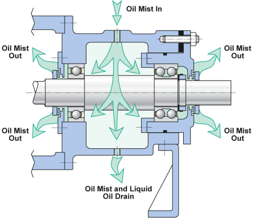
In old-style ‘open’ oil mist systems (Figure 1) the air/oil mixture fills the bearing housing, but not all of the mist passes through the bearings. A portion of the coalesced droplets takes a straight top-to-bottom path through the bearing housing. Only this portion of the coalesced oil and stray mist then exit near the bottom of the housing and can be collected for disposal at the drain location. For bearings to be properly lubricated the oil mist will have to pass through the bearings and then escape at the two unsealed regions where shafts protrude through the bearing housing.
Efforts to simply provide effective bearing housing seals at the ends labeled ‘oil mist out’ in Figure 1 had unexpected consequences for inexperienced users. Oil mist works by causing small globules of lubricating oil to provide an oily coating on the bearing components. However, so as to provide continuous oil replenishment on bearing surfaces, the oil mist must flow and cannot be stagnant, or dead-ended. In ‘old style’ configurations tight-sealing bearing protector seals placed at the ‘oil mist out’ locations (Figure 1) often caused dead-ending. Without oil mist flow there was then neither cooling nor lubricant replenishing on bearing surfaces.
Figure 1. In old-style 'open' oil mist systems the air/oil mixture fills the bearing housing, but not all the mist passes through the bearings.
Old-style (non-API type) oil mist introduction at mid-point of bearing housing Reliability leaders at best-of class companies soon implemented the most ideal routing of oil mist through bearings (Figure 3). This routing became an industry standard almost 20 years ago. Here, oil mist is introduced into the space between a modern bearing housing protector seal and the bearing. Any oil reaching the bottom-center of the bearing housing will have first cooled and lubricated the bearing. Also, having a single centrally located exit hole makes it easy to collect the coalesced oil or residual oil mist. The system is now ‘closed’ and excess oil is ready for filtration and re-use.
The workers’ health guidelines of many industrialized nations permit the relatively small amount of oil mist released from open systems. However, irrespective of prevailing or mandated clean-air requirements an environmentally conscious user would not allow continual releases of oil mist into the atmosphere. Moreover, from a housekeeping viewpoint, it is clearly advantageous not to have smudges of oil on the ground near pumps and other equipment. Oil smudges or rain run-off will reach a waste oil pit and it takes money to extract that oil before the water can be discharged. An open oil mist system thus does not represent best available technology, which is why proven closed oil mist systems technology (Figure 2) is greatly favored today[3].
Figure 2. Closed oil mist system supplying continuous lubrication to pumps and drivers.
Closed oil mist system technology may differ, but Figure 2 incorporates a collecting tank, shown at the far left, to which a return header system is connected. A small blower is provided at the top of the collecting tank and the suction effect of this small blower causes excess or ‘stray’ oil mist to be pulled into the tank. Inserted in the blower is a coalescer maze. Coalesced oil droplets fall out and the oil can be re-used. Only virtually oil-free air is vented to the atmosphere.
Figure 3. API 610-compliant oil mist application at locations between the rolling element bearings and the magnetic dual-face bearing isolators.
Favorable experience
The oil mist routing per Figure 3 together with using either advanced dual face-type ‘fully sealing’ (Figure 4) or axial O-ring valve-equipped bearing housing seals which allow minor ‘weepage’ through the micro lift gap (Figure 5) make closed systems possible. Either way: Forward-looking oil mist users have discontinued ‘old’ oil mist application (Figure 1) since the mid-1970s and have enjoyed decades of superior experience with the routing (Figure 3). The API standards (starting with API 610 / 8th Edition, released in 2000) have recommended oil mist introduction into the region between the bearing and the bearing housing protector seal.
Figure 4. Advanced magnetically-closed dual-face bearing housing protector seal.
Books and articles also describe the unqualified success of oil mist lubrication for electric motors[3, 4]. Contrary to unfounded (and fully refuted) opinions about oil mist attacking electric motor windings or oil mist being a fire hazard, this lubrication method is fully proven to be superior to alternative lube application methods. Closed-loop oil mist best protects industry’s physical plant as well as our environmental assets, whether in spare equipment (standstill) or full operating mode. In best technology closed oil-mist systems, from 97 to 99% of the lube oil is recovered and re-used. These systems emit no oil mist into the surrounding atmosphere and, for years, have been praised by refineries and petrochemical plants concerned about the environment.
Figure 5. Rotating labyrinth-style bearing housing protector seals with axial static sealing O-rings are also suited for use on process pumps and electric motors. A small amount of oil mist can escape past the micro lift gap during operation.
Reliability reaffirmed
In meetings with the primary providers of plant-wide oil mist systems (in 2012 and 2013), the author ascertained that a mere three shutdown incidents were known to have occurred on oil mist systems in two decades of highly successful operation. An estimated average number of 1,800 plant-wide systems have been in service during that 20-year period. The first systems interruption involving a modern plant-wide oil mist system occurred at a US Gulf Coast facility in about 1982.
At that time, a thorough analysis traced the failure to pipe shavings in the 5-gallon capacity misting chamber reservoir. This is where ferrous debris became attached to a magnetic level switch; it prevented the switch from activating a solenoid, which would have allowed oil from a bulk oil holding tank to replenish the much smaller chamber reservoir. When the small reservoir was depleted, none of the connected equipment received oil mist. The bearings ran dry, but did so without incident or bearing failure. It was known that bearings coated with oil in horizontally installed shaft systems can operate for a few hours after discontinuing oil mist had been reported and explained by Allen Clapp(Dow Chemical Company, Freeport, TX) in 1973[3].
These findings were again corroborated in academic research by Shamim and others[4]. Allen Clapp made the additional point that a small pool of oil will exist in the five-to-seven O’clock segment of the contoured raceway in a bearing’s outer ring. Oil mist lubricated pumps can safely stay in service for approximately eight hours before this small pool of oil is depleted. Given that there is ample supervisory instrumentation to annunciate deviations, no modern oil mist system has ever encountered unavailability in excess of eight hours.
The second unavailability event developed at an oil refinery in Enid, Oklahoma, where a single oil mist console was serving two adjacent process units. When the process unit where the oil mist generator (OMG) was located had to be shut down in preparation for scheduled maintenance and repair downtime, the OMG was inadvertently valved off. A day or so later, the adjoining process unit experienced a pump failure. It was then realized that there had been no oil mist supplied for at least 24 hours. The oil mist supply was restored and there were no other bearing failures on any of the connected pumps. The cause of failure was clearly human error; it could have been averted with a simple advisory note posted at the appropriate switch or valve.
A third incident report relates to a Texas Gulf Coast oil refinery where the OMG did not have an automatic fill option. A reservoir refill line connected a bulk storage tank to the small oil reservoir located inside the main oil mist console. An operator (when in doubt, always blame the operator….) decided to crack open the needle valve in the refill line and let it slowly maintain the oil level in the small reservoir. After a period of time, the entire piping distribution system was full of liquid oil; oil had, in fact, displaced the oil mist. About 10 or 12 pump bearing housings and their respective motor driver bearings were filled with oil. A lot of oil was wasted, but there were again no equipment failures in this incident.
Because modern oil mist systems are provided with suitable supervisory instrumentation, no system has ever been disrupted for more than two hours from 2000 until 2015. Overall reliability and availability was calculated as 99.99962 (in 1998) and is now thought to have reached 99.999997%---a number that has never been approached by any other lubrication method [5]. System shut down
The most profitable and reliable plants have found it neither cost nor risk-justified to install oil mist systems with fully connected, ready-to-go spare backup. Nevertheless, some plants ask oil mist suppliers to propose and provide 100% redundancy. In those facilities, a backup or auxiliary oil mist system can be placed in operation on a moment’s notice. Switching from the main unit to a full backup takes 30-60 seconds to complete. The switchover procedure calls for one-quarter turn of the handle of a ball valve. A two or three-sentence procedure sheet is posted on the inside of the cabinet door. The sheet explains what to do in the highly unlikely event of such switchovers ever becoming necessary.
In 2002, one of the authors visited eight petroleum refineries located in the US Gulf Coast region. It was quickly discovered during these visits that oil mist lubrication was the predominant method of lubricating pumps throughout the refining industry in the USA. Also in 2002, an equipment sales specialist with over 20 years experience as a refinery reliability engineer estimated that oil mist was being used by 24 of the 30 refineries in the Beaumont-Port Arthur region of East Texas. He believed that about 80% of the pumps in each facility were lubricated by oil mist systems. One US West Coast consulting engineer with considerable background as a refinery engineer estimated that about 50% of all USA refineries were using oil mist in 2001.
As of 2015, many of these refineries have now employed closed systems oil mist technology for over four decades and are calling this application method an unqualified success. The refineries consider closed oil mist systems a competitive advantage and have fully endorsed the application routines illustrated in this article. Moreover, these users are doing their part towards achieving a cleaner environment while imparting reliability to their rotating equipment assets.
What else could cause an oil mist unit or system to shut down? Well, one manager added to the three events spelled out earlier. He said running a fork lift into the 2in oil mist header would shut the system down. That may be true but certainly has never happened on any of the estimated 3,000 plant-wide oil mist systems now in service all over the world. And if it did happen, it would take considerably less than eight hours to repair the low-pressure non-flammable oil mist header.


