
A pdf version of this article is available on the right-hand side under 'Downloads'
In June 2005, the requirement of a 17 m long vertical pump for a new sulphur tank at the ship unloading terminal in Helsingborg, Sweden came about due to an accident at the plant of Kemira Kemi AB. A damaged water supply pipe caused strong ground erosion resulting in a collapsing sulphuric acid tank. The site was flooded with sulphuric acid and the tank farm, including the horizontal pumps installed on the ground, was badly damaged. As a result, a risk analysis was carried out and a new safety concept had to be developed.
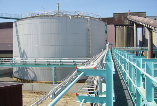
Special solutions cover a wide range of different installations. For sulphur tanks/pits installed below ground level it is common practice to use a vertical pump type if centrifugal pumps are required. Different designs of vertical pumps are available. An 11 m long vertical pump has been running maintenance-free since 1998. The new tanks required a pump installed on the top of the tank (Figure 1) and other features including:
• Beams that carry the roof on the outside to avoid sulphur solidification on the structure on the inside.
• Hanging steam pipe coils from the roof for heating the sulphur.
• SO2 detectors on the roof and temperature measurement on the inside of the tank to prevent possible fires.
• A steam system to turn down fires inside the tank activated from the control room.
Design
When designing a pump for molten sulphur, it is important that the properties of sulphur are taken into consideration. Due to the abnormal variation of viscosity with temperature, sulphur can only be pumped satisfactorily within the 135-155 °C range. Most pumps used for molten sulphur applications have a heating jacket in order to keep the temperature constant in all parts of the pumps. The presence of Hydrogen Sulphide (H2S) directly influences the temperature range, in which sulphur can still be pumped with an acceptable viscosity.
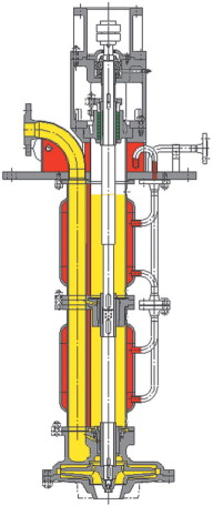
Generally, vertical centrifugal pumps (Figure 2) have some unique design features to ensure trouble free operation and easy maintenance. The discharge and the shaft column are built as a complete steam heated unit to give optimum stability, especially for pumps longer than 2000 mm and to maintain the required temperature for molten sulphur. In addition, vertical pumps should have a double volute casing, which minimizes the radial forces, which results in lower wear of the sleeve bearings. This increases the mean time between failures (MTBF) for these pumps. Materials for molten sulphur pumps vary from cast iron, cast steel and stainless steel depending on the application.
After clarifying all technical details, the design of the pump was started. A suitable hydraulic (100/315) was chosen to deliver a capacity of 70 m3/h at a head of 22 m. 11 sulphur lubricated sleeve bearings were necessary to stabilize the entire shaft.
The 17 m long pump is equipped with three independently fed steam heating jacket sections to provide a temperature equilibrium throughout the entire system without condensation. The growth of the pump when heated to operating temperature should not be underestimated. In this case, the pump will expand by 30 mm. Materials with similar heat expansion coefficients must be used to avoid internal stress caused by unequal thermal expansion coefficients.
All column sections and steam lines were flanged together, not welded. This allows for easy assembly/disassembly and maintenance. Each section of the pump was equipped with drain holes to ensure the complete drainage of the unit to avoid solidification of sulphur when the pump is removed from the tank.
The soleplate had to be designed to be able to carry the entire weight of the pump under operating temperature parameters. Special shaft designs had to be used to connect the single shaft pieces and to allow reverse rotation (caused by reverse flow when the pump has been shut down). For these types of long shafted pumps, it is essential to perform Finite Element Analysis (FEA) studies before the design is finalized and production is started.
One of the main studies was the modal analysis, which described the dynamic behaviour of the entire system. Natural frequencies can be detected, and speed areas where the pump should not be operated can be determined. With the FEA method it is also possible to calculate the thermal expansion properties, which are dependent on the liquid levels in the tank. Figure 5 shows the deformation of the entire system caused by a frequency of 27,6 Hz.
Separately from the calculations of the entire pump system, the pump shaft design (e.g. material, diameter) and the sole plate also had to be checked by calculations. The position of the sleeve bearings have to be verified, as they act as guide bearings to break up the harmonics, so their radial load is minimal. After performing all necessary calculations with state-of-the-art software, the design was finalized and the pump was released for production.
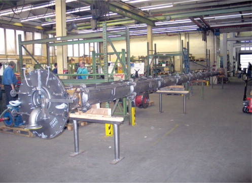
Eleven sections of the column were manufactured separately. For these types of long shafted pumps, the parallelism of the connecting flange surfaces is an essential criterion to guarantee the concentricity of the entire rotating unit after assembly.
Each section consists of pipes, bumped boiler ends and flange pieces which also carry the sleeve bearing bushings. The shaft components are machined separately and the shaft run-out should be smaller than 2/100 mm. The impeller is trimmed to the rated diameter and is balanced after according to DIN ISO 1940 T1 G 6.3 or G 2.5. Material combinations, design of the grooves in the bushings (e.g. spiral or slot) and the bearing clearance is essential for the service life of the sulphur lubricated sleeve bearings.
After manufacturing the units, the pump was completely assembled to check the tolerances and the fitting accuracy. It was possible to turn the shaft by hand while the pump was in a horizontal position (Figure 4).
After marking and disassembling the sections, a short version (6 m) of the pump was tested. The components below the sole plate received a rust-preventative coating which is suitable for direct contact with molten sulphur after installation.
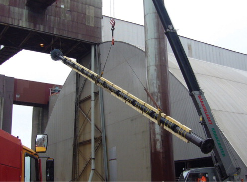
The pump was shipped in single parts to the site and once more assembled. After assembly, the pump was stabilized with wooden beams to avoid possible deflection during transportation and installation. It was then loaded on a flat bed trailer and transported from the shop to the tank.
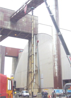
Two cranes were positioned at the tank farm to bring the pump from a horizontal into a vertical position. One crane was equipped with a special deflection pulley and the other cranes duty was to start lifting the sole plate end (Figure 5). After reaching the final vertical position, only one crane was needed to lift the pump into the manhole of the new tank at the ship unloading facilities (Figure 7).
In principle, there are two ways to install the pump; in new systems, the tank is normally empty. If the tank is already full (often during equipment maintenance) the recommendation is not to lower the pump faster than 10 cm per minute, at a pump length of 17 m this results in almost three hours lowering time. Also, the pump heating jackets should never be used to heat up solid molten sulphur in the tank.
Final positioning
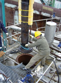
In this case, the tank was empty and the pump was lowered at a speed were it still was possible to take the wooden supporting beams off. It was important to check the flange surface at the manhole with a water level before installing the pump to ensure an exact vertical installation. After the sole plate reached its final position at the manhole (important not to forget the gasket!) washers were added and the screw nuts were fastened cross-over with the recommended torque. After that the sole plate was insulated.
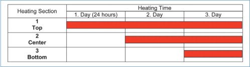
After the steam lines were connected, the pump was ready to be heated up. If the steam is turned on, the shaft will normally reach a temperature of 150 °C in 15 hours. For pumps of this length, special heating cycles have to be followed (see Table 1), otherwise the column and discharge pipes would grow much faster than the shaft itself and shear the impeller off. For the design of the pump, special provisions were taken for the impeller gap considering the different growth of shaft and pipes.
After pump heating, the motor was connected and a decoupled rotation test was performed. It is also mandatory to turn the shaft by hand to ensure it is freely turning before the pump is coupled and started. If this is the case and the pump can be started up, it is recommended to do so against a closed discharge valve.
Inside the tank, care must be taken to ensure that there are no fixtures (like steam heating coils) within a certain distance of the pump. Once the pump is started it will start to orbit over its full length. Therefore, it is very important that the pump is suspended freely from the sole plate to the bottom of the pump.
After the rated duty point is achieved, vibration measurements should be taken at the locations specified in the relevant standards (e.g. DIN ISO 10816-3).
Conclusion
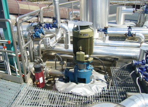
Since its start up in May 2006, the pump runs successfully accompanied by monitoring of vibration and flow. The 17 m vertical pump is being used to pump liquid sulphur from the main storage tank at the port to the sulphur burner feed tank at the sulphuric acid plant. The entire safety concept proved to be a reliable solution for the increased safety demands on site.


