
The demand for water and sanitation in the world's major cities are climbing constantly as they deal with the challenges of increasing population and rapid urbanization. In addition, spreading urbanization causes the loss of forests in the surrounding mountains, which leads to decreasing rates of storm water percolation. It also increases the amount of wastewater to handle and treat. Soil subsidence and storm water surges threaten to collapse the existing infrastructure.
In Mexico City, this demand has largely been met by a growing system of wells drilled into the soft aquifer underlying the region. This intense exploitation has significantly lowered the ground — up to 50 cm per year in some areas. Two large combined waste water pump stations relief hundreds of thousands people from damages through floodings during the raining season and form part of the millennium infrastructure project in the Valley of Mexico.
Mexico's water authority conducted extensive feasibility studies and finally specified the world's biggest submersible motor pumps. Results from basic research projects were used as a basis for an initial layout. State of the art hydraulic engineering tools were utilized to ensure a reliable and efficient operation.
Background
The Mexico City metropolitan area is one of the largest urban concentrations in the world. It is located inside a basin consisting of the Texcoco, Xaltocan, Zumpango, Xochimilco and Chalco lakes. The five lakes used to become one and cover a total surface of two thousand square kilometers. After the rain season (May to October), when the water of the lakes evaporates, the lakes become smaller in size.
With the aim to control the flooding events, the Spanish Colonists constructed the first artificial output, the so called ‘Tajo de Nochistongo’, at the late XVIII century. During the last decades of the XIX century, after Mexican Independence, the ‘Gran Canal del Desagüe’ was excavated and the first tunnel of Tequixquiac was built. Both works were inaugurated in March 1900 to discharge residual waters and rain water to a bordering basin, located 50 km to the north of Mexico Valley.
This system was reinforced with a second tunnel that began operations in 1947. In 1962 and 1975, the first two tunnels of deep sewage started operation, the: ‘Emisor Poniente’ and ‘Emisor Central’.
Today, the Metropolitan Area of Mexico City Valley (ZMVM) covers a surface of 1,894 km2, almost the 22% of the valley and the 95% of the surface occupied by the lakes in the XVI century.
The ground of the valley is formed by soft clay with a high content of water, highly deformable and compressible, caused by the extraction of underground water to supply the city. This activity has produced subsidence and differentials that strongly affect the urban infrastructure.
Downtown Mexico City subsides at a 10 cm per year rate while the subsidence of the ground on the old Chalco Lake, has reached 60 cm per year. This condition has reduced the capacity of the superficial sewage conducts, affecting the ‘Gran Canal del Desagüe’ and the superficial canal called ‘Río de la Compañía’, that attend the center and south orient regions respectively.
‘Río de la Compañía' and 'La Caldera'
The ‘La Compañía’ river is the main rain and waste water output from the south east area of Mexico City Valley. It flows through highly populated areas and begins at the joint of San Francisco and San Rafael rivers, at the east of the Chalco valley basin. The river ends at the ‘bordo Xochiaca’, where it joins with the canal system of Texcoco lake.
The section of the ‘La Compañía’ river that was damaged by soil subsidence is located between the rocky formations of Tlapacoyan hill and “La Caldera” Vulcano.
In March 2000 and February 2010, huge fissures on the left border of the river caused serious flooding in the populated area around.
The Federal Government of Mexico and the Local Government of Mexico State joined forces to combat flooding caused and developed two major projects:
• ‘La Compañía’ river tunnel with 5 m diameter, 7 km length, 20 m under the ground level to transport up to 40 m3/s.
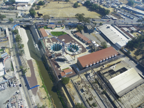
• ‘La Caldera’ pumping plant to raise the water transported by the tunnel to the ‘La Compañía’ river, after the section damaged by subsidence. The river transports the water to the former Texcoco lake area, and then it is transported outside from Mexico City Valley.
• Ten collectors of rain and waste waters, that feed the tunnel.
• ‘La Gasera’ regulation dam, located in the joint of the San Francisco and San Rafael rivers, that allows to redirect up to 30 m3/s to ‘La Compañía’ river.
Added to this, to make the tunnel and pumping plant maintenance possible, the borders of the canal have been retired and a new closed conduct is been built on the original location to transport the sewage waters during the dry season.
Eastern Outfall tunnel and ‘El Caracol’ pumping plant
The capacity of the city's drainage system is not enough. In 1975, when the metropolitan area's population reached 10 million, the capacity of the system was 280 m2/s. Today, the population has climbed up to double the amount but the capacity has been reduced to 195 m2/s.
To protect the area against flooding events, the sewerage system managing waste and rain water must have a capacity of 315 m2/s. Because of this, Mexico Federal Government decided to build the Eastern Outfall Tunnel with a capacity of 150 m2/s. This project will also allow the alternated maintenance of the central and eastern tunnels during the dry season.
A first stage of the ‘Emisor Oriente’ tunnel, with 10 km length, is scheduled to start operations in December 2012. The ‘El Caracol’ pumping plant is in construction to offer a protection of 40 m2/s to the population. This plant will raise the water transported by the tunnel to the Gran Canal in a section where the subsidence is not a problem and can take the water out of the Mexico City Valley through the Tequisquiac tunnels.
In conclusion, ‘La Caldera’ and ‘El Caracol’ pumping plants were both designed to pump 40 m2/s. They raise the water from the bottom of a tunnel to a superficial canal and include deep shafts of 30 m and 54 m, respectively. For both cases, it was decided to install submergible engine pumps to ensure better pumping availability, facilitate the maintenance and reduce the failures in long metallic columns.
Each of the pumping plants receives water from the tunnel, in a shaft with mechanical grids that distributes water to two pumping shafts with a capacity of 20 m2/s each.
Each pumping shaft of ‘La Caldera’ pumping plant, is equipped with four pumps of 1 m2/s and 8 pumps of 2 m2/s, while the pumping plants of ‘El Caracol’ are equipped with 10 pumps of 2 m2/s each of them.
Pump station design
The requirements for intake structures depend on the respective field of application. For sewage and waste water pumping stations boundary conditions normally differ from boundary conditions of cooling water systems. Two important differences are:
• Strongly varying water levels: While in cooling water system water level normally depend on the water level of touching open water flow (sea, river,…), sewage water pumping stations are charged irregularly in different strengths.
• Solid transport: the compositions of waste water are different from cooling water as much more solids and organic components can be found in waste water.
The basic design of waste water pumping stations should guarantee that installed pumps are running with sufficient inflow conditions and, in addition, avoid any form of heavy sedimentation or, in some cases, floating sludge. In comparison to cooling water system no fine mesh cleaning devices are used. Therefore all solids and organic components have to run through the intake structure and the pumps.
On the basis of practical experience and basic research a steady improvement of standards and planning documents is necessary. Due to cost and time issues the volumes of intake structures are reduced more and more while the flow rates increase. This effect leads to an increased energy content of the intake flow.
Different basic recommendations for various waste water applications have been developed by institutes and manufactures and have been implemented in praxis over the past years.
As an example, the development of a compact waste water intake structure with lateral inflow[1] can be mentioned. During this basic research project the capacity of the structure to provide the installed pumps with equal flow conditions, although the structure is charged with 90° towards the inflow direction of the pump, was tested and improved. Several physical model investigations, as they are state of the art for optimization and documentation processes of intake structures, were done to improve the design of an installed tossing chamber for all operating points.
The result of these researches is the need to decouple the boundary inflow conditions from the pump sump flow conditions as boundary conditions change from project to project. During design process improvements of the direct inflow conditions into the pump are done in a separate step normally.
Sedimentation and floating sludge
As mentioned before the occurrence of sedimentation and floating sludge are main differences between waste water and cooling water pumping stations. To avoid these negative effects two main approaches are common:
• By installing flow guiding devices, for example berms or slopes, the flow containing solids gets directed to the accelerated flow in the area of the installed pumps. These installations have no influence on the operation conditions of the pumps.
• By reducing the flowed through volume inside the intake structure, reducing chamber width or inflow diameters, flow velocities should be adjusted as high as transported solids cannot settle.
The flow acceleration towards the pump sump should be realized at ground level in a way that the ground is free from solids. In practice a straight charging of the pump sump with high velocity flow is not always possible. To avoid insufficient charging of the pump, for example increased swirl, flow guiding devices, such as floor splitters or cones, should be installed under the inlet nozzle of the pumps. Pump sump designs are mostly standardized by manufactures and institutes with mostly no significant differences. So the challenge during intake design process is to install sufficient interface conditions between the inflow' defined by local boundary conditions' and the pump sump flow.
Summing up it can be said that the designing process of waste water pumping stations is more challenging than the designing process of cooling water pumping stations.
In the following section a practical example is given where a design and optimization process for a waste water pumping station was done with the use of physical model investigations and numerical approaches (CFD).
The initial scope of work was the hydraulic design of two different waste water pumping stations in Mexico City. Both round shaped stations consist of a dry and a rain weather section to solve changing load cases causes by changing weather conditions. The design and optimization process of one station is subject of the following, as it is similar for both stations.
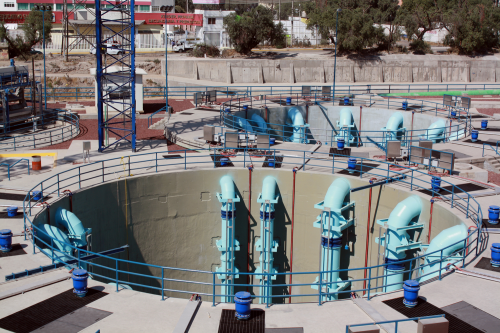
The prototype water intake system consists of a circular building with ten submersible motor pumps installed. The raw water enters the intake structure through an inflow pipe with a diameter of 5000 mm. Through a cone with feeding openings the inflow is portioned to the single pumps.
The structure is divided into two sections (4+6 pumps). The dry weather section is placed in the area of the inflow section. Two pumps at each side are fed by a separate inflow channel. A dividing wall with openings separates both sections. On a circular area of 20 m diameter, the ten pumps are installed at the outline contour to cope with a maximum of 20 m3/s incoming flow during rainy season and 2 to 8 m3/s during dry weather season.
The separation of dry weather and rain weather sections is necessary to guarantee minimized sedimentation for periods of dry weather as all solids have to run through the high velocity area of the dry weather section. By increasing flow rates the rain weather section will be charged. Due to structural issues both sections can exchange flow at upper levels through smaller holes.
In summary it can be said that due to the split up of the complete structure into two separate sections, with different boundary conditions; the flow guidance of the complete structure becomes more flexible. This is mandatory as the charging of the station is very irregular.
The initial layout of the structure was investigated by numerical approaches and physical model investigation as a combination of both methods is state of the art nowadays. The numerical and the physical models are shown in the figures below.
The physical model was designed as a Froude model (FrPrototype = FrModel) with a scale factor of 1:10. The Froude number describes the ratio between inertia und gravity forces, therefore effects dominated by these forces can be transferred from the model to the prototype.
Evaluation
Vortimeters (four blade propeller) were installed at impeller elevation to detect the strength of rotational flow around the axis of the suction pipe. Flow through the model was produced by a circulation pump outside the test tank. Due to size limitations no velocity measurements were done inside the model pump. The evaluation of velocity distributions inside the inlet nozzle and inside the whole intake structure were done with results of numerical approaches. All CFD work was done with state of the art software and approved boundary conditions and adjustments. While during the model tests all possible operating points were investigated and documented. CFD was used for the visualization of selected and significant conditions.
To guarantee flow velocities that do not allow transported solids to settle, the number of pumps running depends on the water level (used volume) inside the structure.
By installing additional baffle plates and by increasing the floor splitter heights sufficient flow conditions could be adjusted even at areas of significant separation flow.
All state of the art recommendations concerning flow guidance and in this way inflow conditions could be fulfilled. No free surface effects, such as air entrainment, could be observed. No vortex systems not in accordance with state of the art specifications occurred.[2]
Bibliography
1. K. Kirst, D.-H. Hellmann, B. Kothe, P. Springer, Physical Model Investigation of a Compact Waste Water Pumping Station, ICPF 2010, Hangzhou, China, (October 2010).
2. G.E. Hecker: Fundamentals of vortex intake flow, Swirling flow problems at intakes, IAHR, Hydraulic Structures design man.
Uncited references
3. P. Springer, T. Koch, Influence of aeration on the operating conditions mixers in activated sludge tanks.
International Rotating Equipment Conference
This paper was first presented at the 2nd Pump Users International Forum held in Düsseldorf, Germany, September 2012 and is reproduced with permission from VDMA eV.


